
The author rendered the mazes in graphical form using a Ruby library that allows you to create PNG images. This requires you to run the code, then open the saved image, then remember to close it before running the code again, otherwise you get a "File access denied" error, all of which seemed like hard work. As I work with WPF on a day-to-day basis, I decided to use that to render my mazes, as it was quicker and easier.
I took the opportunity to refactor my code, as it was all in one console application at this point. I moved the classes for the basic units, such as Grid and Cell to a class library, along with the factory classes for the two algorithms I had implemented so far. As WPF contains a UI element by the name of Grid, I decide to rename my class to Maze, to avoid any ambiguous naming. As it happens, I think this is a better name.
For simplicity, I did the rendering in the code-behind, rather than implement MVVM, which would be my normal choice for WPF. As the initial version of the code would not really need any UI controls, there was no benefit in adding an extra layer of complexity at this point.
I used a similar algorithm to the author's, more because it's a basic approach than because I copied his code, as I wrote this bit myself. I found trying to translate his use of Ruby and the external package to be too far removed from what I was doing, and worked it out myself. This was quite challenging, as I don't normally do this kind of thing, but turned out to be fairly straightforward, once I convinced myself to think before coding!
The XAML looks like this...
<Window x:Class="Mazes.UI.MainWindow"
        xmlns="http://schemas.microsoft.com/winfx/2006/xaml/presentation"
        xmlns:x="http://schemas.microsoft.com/winfx/2006/xaml"
        xmlns:d="http://schemas.microsoft.com/expression/blend/2008"
        xmlns:mc="http://schemas.openxmlformats.org/markup-compatibility/2006"
        mc:Ignorable="d"
        Title="Mazes For Programmers"
        SizeToContent="WidthAndHeight">
  <Grid>
    <InkCanvas Name="Canvas"
               Height="800"
               Width="800"
               Margin="5"
               Background="LemonChiffon" />
  </Grid>
</Window>
There's nothing of particular note here, other than my discovery of the InkCanvas UI element. This works like a regular Canvas element (ie allows you to draw shapes on it), but has the extra feature that when the code runs, you can draw on the canvas with your mouse! This provided some childish amusement as I solved the mazes I had generated. If you don't want this feature, you can use a regular Canvas element instead. It will look the same, but not allow you to draw at run-time.
At this stage, I was still hard-coding the maze size in the XAML file's code behind. At some point, I would like to implement a decent UI, where you can choose the canvas size, number of cells, generation algorithm, etc, but I'm not there yet.
The code to draw the maze was quite straightforward...
    private void DrawMaze() {
      Width = Canvas.Width + 2 * Canvas.Margin.Left;
      Height = Canvas.Height + 2 * Canvas.Margin.Top;
      int hCells = 5;
      int vCells = 5;
      Maze maze = Sidewinder.Create(vCells, hCells);
      double hCellSize = Canvas.Width / hCells;
      double vCellSize = Canvas.Height / vCells;
      // (0, 0) is top-left
      for (int row = 0; row < vCells; row++) {
        // (hOffset, vOffset) is the top-left of the current cell
        double vOffset = row * vCellSize;
        for (int col = 0; col < hCells; col++) {
          double hOffset = col * hCellSize;
          Cell thisCell = maze[row, col];
          if (!thisCell.Linked(thisCell.South)) {
            DrawLine(hOffset, vOffset + vCellSize, hOffset + hCellSize, vOffset + vCellSize);
          }
          if (!thisCell.Linked(thisCell.East)) {
            DrawLine(hOffset + hCellSize, vOffset, hOffset + hCellSize, vOffset + vCellSize);
          }
        }
      }
      DrawLine(0, 0, Canvas.Width, 0);
      DrawLine(0, 0, 0, Canvas.Height);
    }

    private void DrawLine(double x1, double y1, double x2, double y2) {
      Line line = new Line { X1 = x1, Y1 = y1, X2 = x2, Y2 = y2, Stroke = _brush, StrokeThickness = _line };
      Canvas.Children.Add(line);
    }
It is important to note that this will only work if you manually set the size of the Canvas, either in the XAML or in the C#. If you allow WPF to size it, the Height and Width properties will be NaN, which makes the maths a little, erm, interesting!
The first two lines set the size of the window so that the canvas neatly fits. After setting the number of cells and generating the maze (which will hopefully be covered in another blog post), we calculate the size of each cell in pixels.
We then loop through the rows and columns. For each cell, we draw a line below if there is a link to the cell to the south, and line to the right if there is a link to the cell to the east. For cells in the right-most column or bottom row, the east and south borders (respectively) will always be drawn, giving us two outside borders. We end by drawing the left and top borders, which will have been missed by the loops.
The result of this was reasonably pleasing for someone who isn't much of a graphics designer...
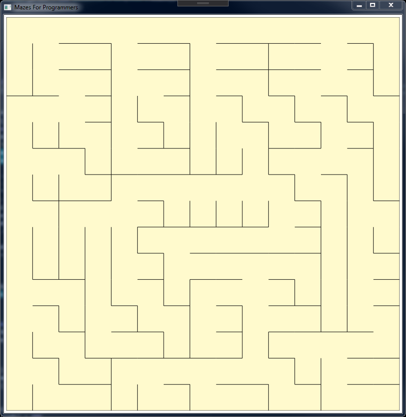
There is a lot of scope for improvement here, but as I'm doing this for the fun of it, and not to produce a commercial application, I'm not going to spend too much time spiffing it up.
Comments
No approved comments yet.